MODELLING
Sample data: Download
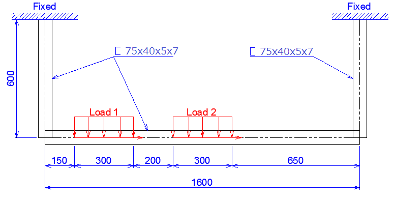
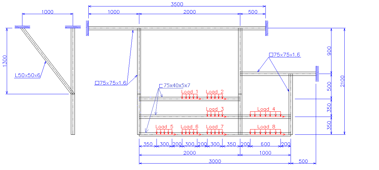
Problem: This problem involves making model. The frame has size and loading as show below.

-
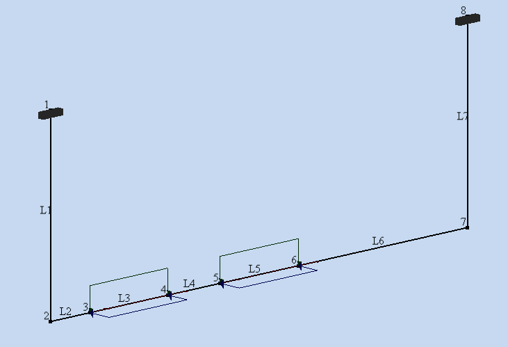
Create point and add line:
-
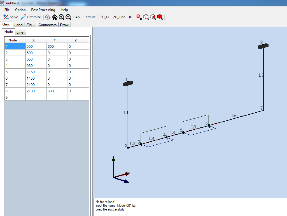
Under [Geo] tab select [Node] tab.
-
In the coordinate box, input coordinate of node. Pres [Enter] to accept.
-
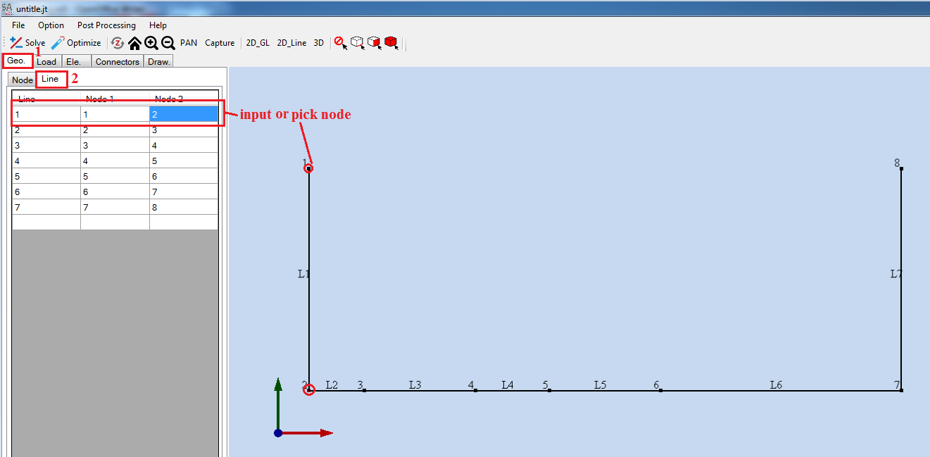
In screen, click right mouse and select [Add line]. Pick two node to add line. (Or select Line tab and input two node of line.)
Table of node coordinate:
|
Node ID |
X |
Y |
Z |
|---|---|---|---|
|
1 |
500 |
600 |
0 |
|
2 |
500 |
0 |
0 |
|
3 |
650 |
0 |
0 |
|
4 |
950 |
0 |
0 |
|
5 |
1150 |
0 |
0 |
|
6 |
1450 |
0 |
0 |
|
7 |
2100 |
0 |
0 |
|
8 |
2100 |
600 |
0 |
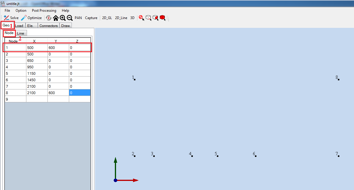
Table of lines:
|
Line ID |
Node 1 |
Node 2 |
|---|---|---|
|
1 |
1 |
2 |
|
2 |
2 |
3 |
|
3 |
3 |
4 |
|
4 |
4 |
5 |
|
5 |
5 |
6 |
|
6 |
6 |
7 |
|
7 |
7 |
8 |
-
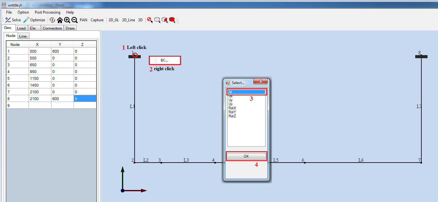
Boundary:
-
Left click node [1] and right click in screen.
-
Select [BC].
-
Select [All] and click [Ok].
-
Replace with node 8.
-
Loading:
-
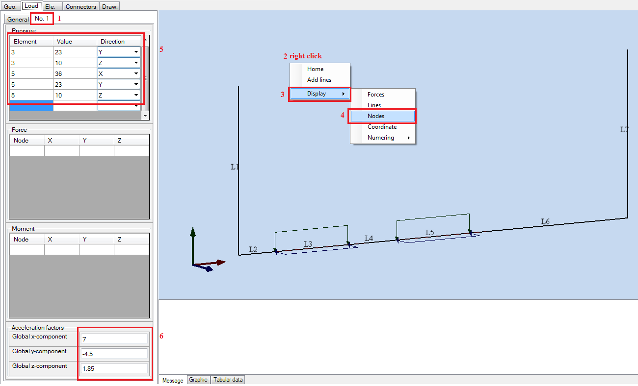
Under [Load] tab, select [General] tab and click [Add new load].
-
Select [No.1] tab.
-
In screen [Right click] and select [Display] > [Node] for [Hide ] the Nodes.
-
Under [No.1] tab, in [Pressure] table input the following element id, value and direction of pressure.
-
In Acceleration factors table input Global x-component = 7, Global y-component = -4.5, Global z-component = 1.85.
Table of pressures:
|
ELEMENT |
VALUE |
DIRECTION |
|---|---|---|
|
3 |
36 |
x |
|
3 |
23 |
y |
|
3 |
10 |
z |
|
5 |
36 |
x |
|
5 |
23 |
y |
|
5 |
10 |
z |

-
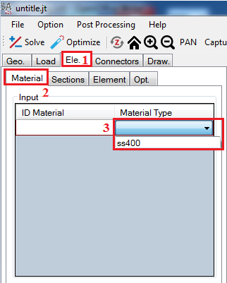
Material:
-
Under tab [Ele.], select [Material] tab and click on [Material type], select [ SS400].
-
Export template file:
-
Click [File] > [Export] template file.
-
Input [File name] then click [Save].

-
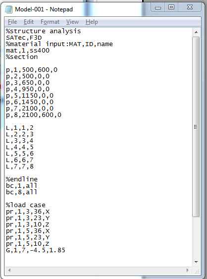
Description of keywork input:
-
Open file save Model-001.txt in step 5.
Definition of function:
- Starting with % signs are the note.
Table of table definition:
|
FUNCTION |
DEFINITION |
|
SATEC,F3D |
+ SATEC: Soft's name + F3D: Type of analysis is FEM 3D |
|
mat,1,ss400 |
+ mat: material + 1: Material ID + ss400: type of material |
|
p,id,x,y,z |
+ p: point + id: point ID + x,y,z are point coordinate |
|
L,id,node1,node2 |
+ L: line + id: Line ID + node1 and node2: first point and second point of line. Use node ID for node1 and node 2. |
|
bc,id,dof |
+ bc: boundary conditions + id: point ID where put boundary. + dof: degrees of freedom (all is fixed 6 dof Ux, Uy, Uz, Rotx, Roty, Rotz) |
|
pr,case,element,value,direction |
+ pr: pressure. + Case: Load case + Element: Line ID where put pressure. + value: value of pressure. + direction: x-direction, y-direction or z-direction. |
|
G,case,x-value,y-value,z-value |
+ G: Gravity + case: Load case. + x-value, y-value and z-value are value gravity follow derection x,y,z. |
|
F,case,node,Fx,Fy,Fz |
+ F: Force. + case: Load case + node: force node. + Fx,Fy,Fz: direction value of force. |
|
M,case,node,Mx,My,Mz |
+ M: Moment. + case: Load case + node: moment node. + Mx,My,Mz: direction value of moment. |
DRAWING
Sample data: Download
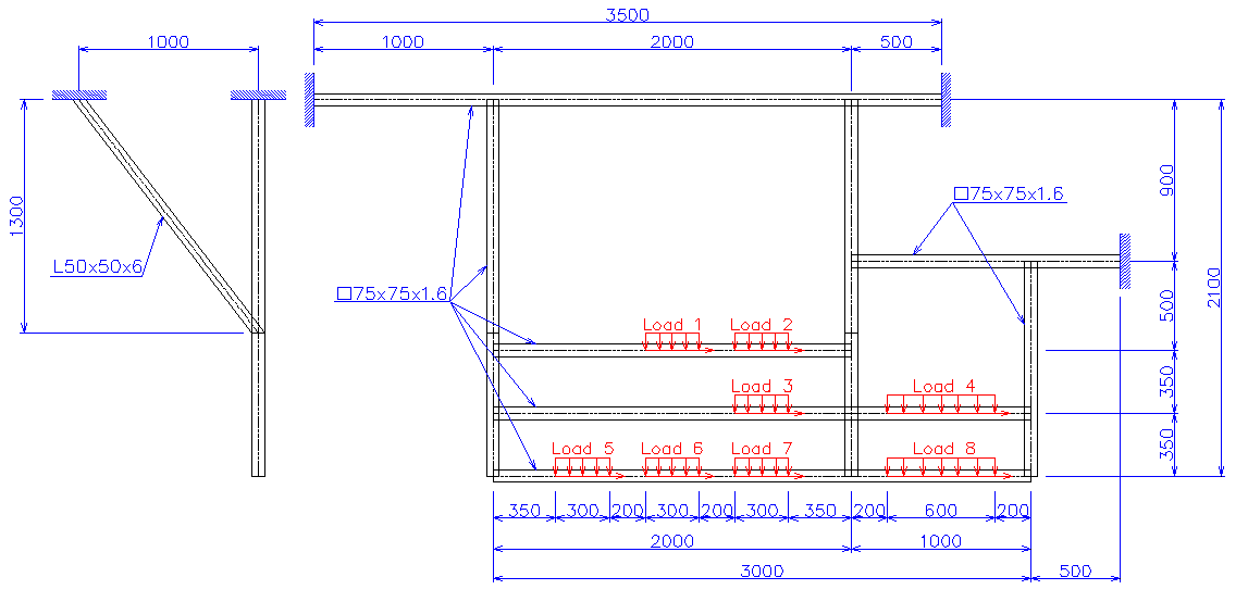
Problem: This problem involves drawing tools. The frame has size and loading as show below.

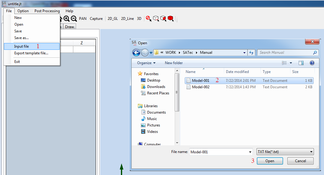
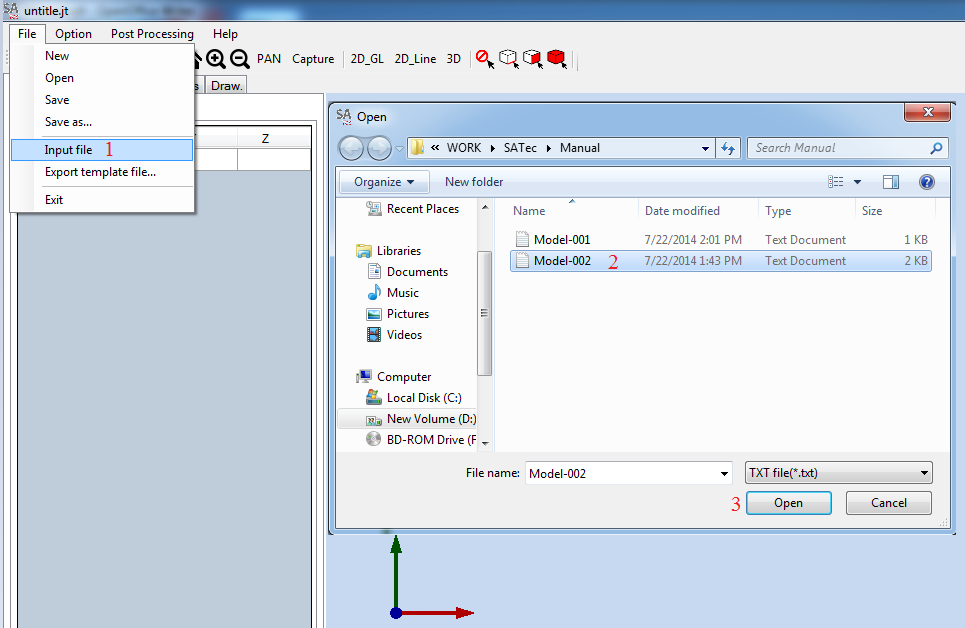
Input model File:
Start SATec and activate the File>Input function of the main menu, to read the model file. The File Manager window appears. Navigate and select the file Model-001.txt.

We have a Model

Create a Section:
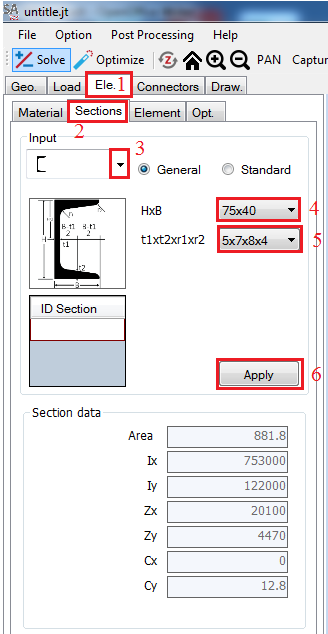
Select tab [Ele.] > [Sections], under label [Input] click on drop down box and select [Channel] section.
[Dimension] is select [75x40] and [Thickness] is select [5x7x8x4].
Click [Apply].
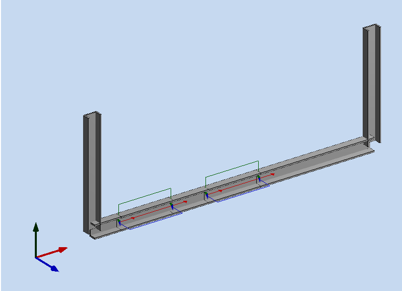
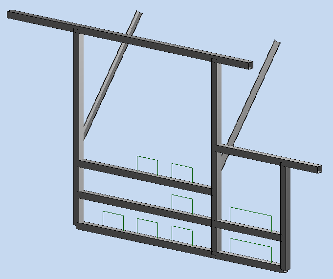
Select [3D] view to see 3D model.
![]()
3D model:
Group element:
In [Ele.] tab click [Element] tab.
Click on [Select]. Screen pick beam G2, G3, G4, G5 and G6. Select [2D_GL] to show a label of beam.
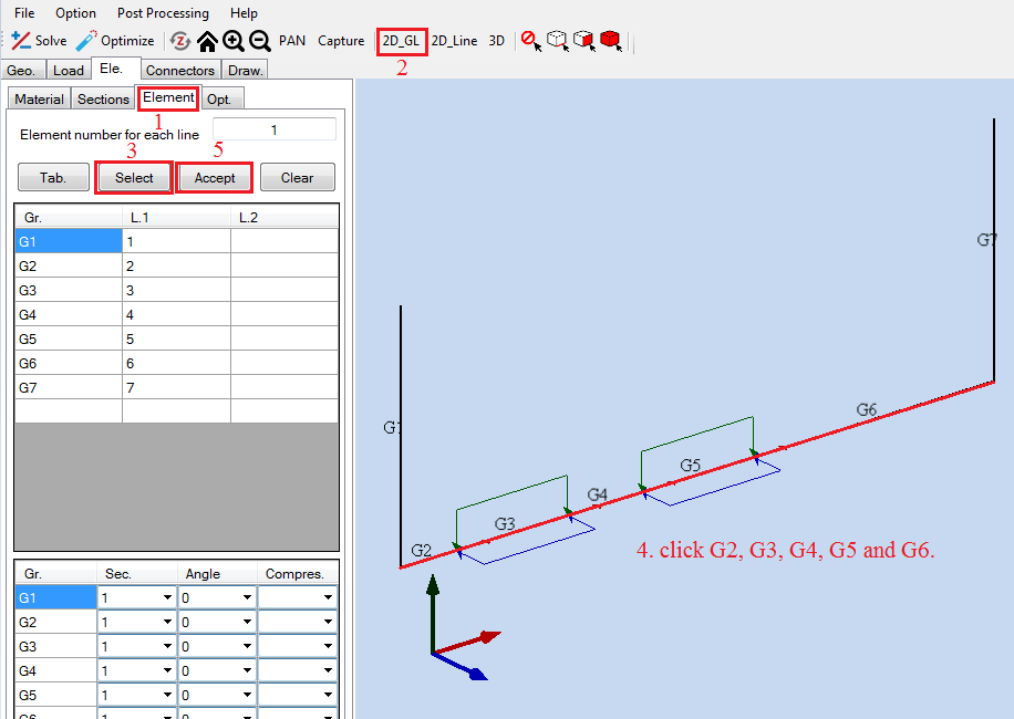
Cick [Accept] to creat a group.
Click [2D_GL] againt and rotate beam G1 an angle of [1800].
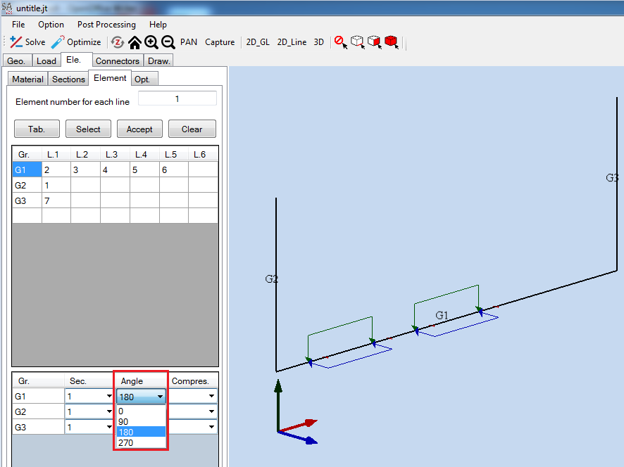
Click [3D] to show a new model.

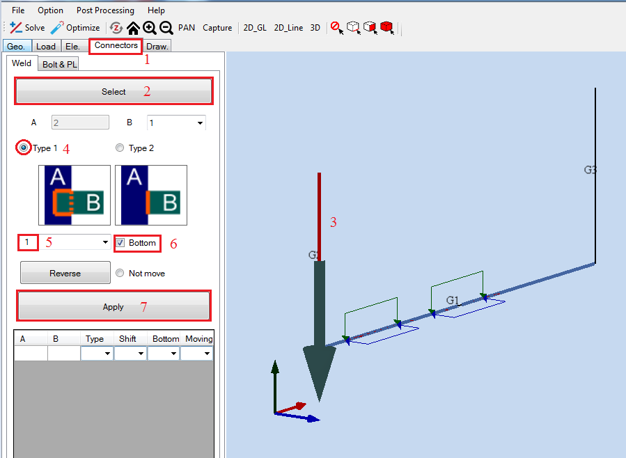
Create a welding:
Click [Connectors] tab.
Click [Select]. In screen click beam G2].
Choose [Type 1] and check in [Bottom].
In drop down box choose value [1] and click [Apply].
Replace with beam G3, but in drop down box select value [-1].

We have:

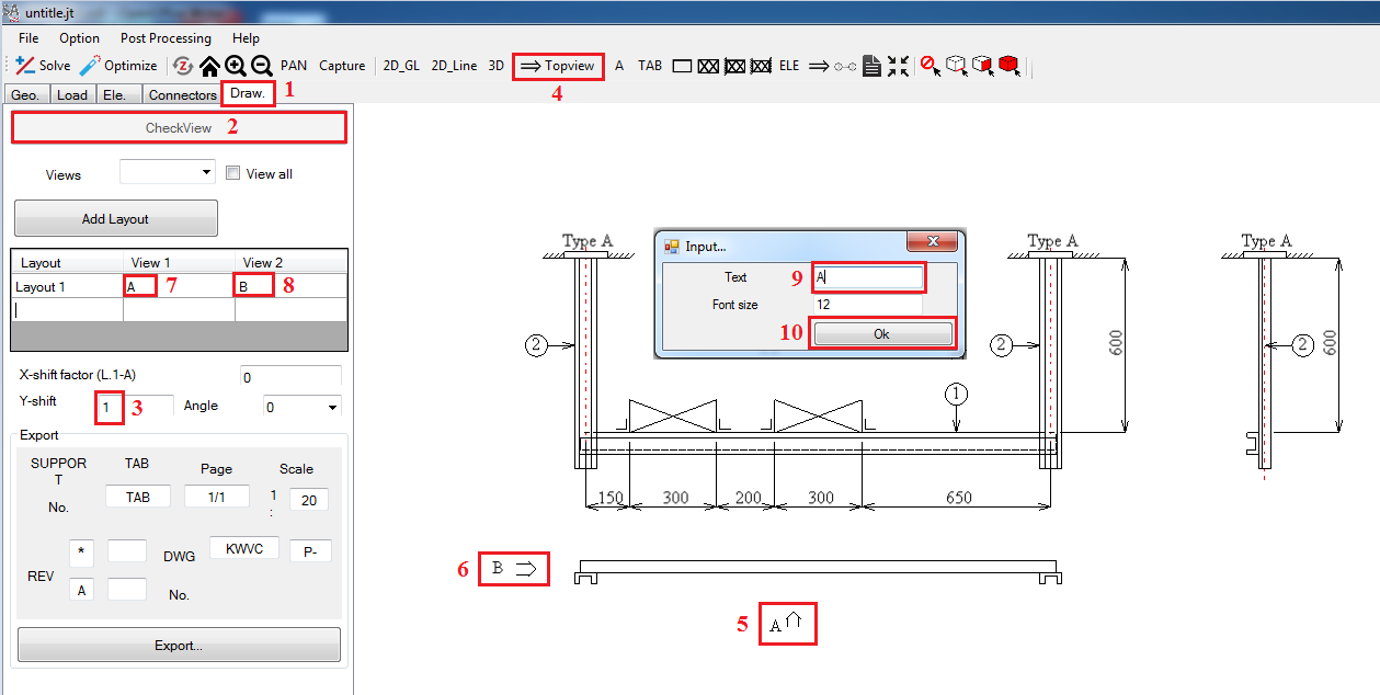
Drawing:
Select tab [Draw].
Under tab [Draw] click [CheckView].
Click in [Y-shift] and input [3].
Click on
 for scale model. Input [2] as the scale factor dialog box then click
[Ok].
for scale model. Input [2] as the scale factor dialog box then click
[Ok].
Select [Topview]. Screen click two point, in dialog box [Input A]. Replace to make View [B].
In [Layout] table, click in [View 1] and input [A], click in [View 2] and input [B].
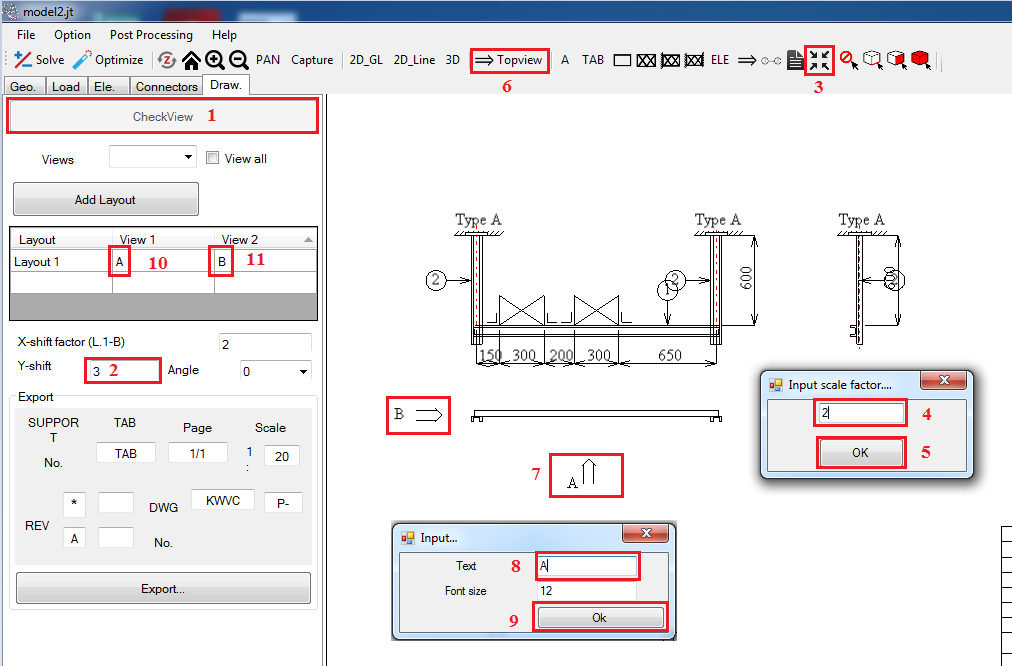
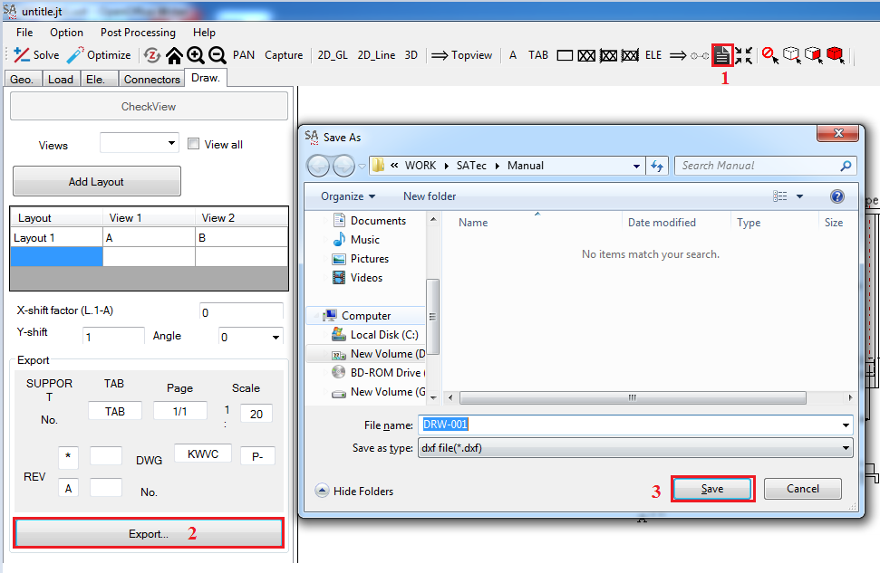
Select

Click Export.
Fill a File name "DRW-001" and click Save.
BOLT AND PLATE
Sample data: Download
Problem: This problem involves using bolt and plate tools. The frame has size and loading as show below.


Input model File:
Start SATec and activate the File>Input function of the main menu, to read the model file. The File Manager window appears. Navigate and select the file Model-001.txt.
We have a Model

Create a Section:
Select tab [Ele] > [Sections], under label [Input] click on drop down box and select [Chanel] section.
[Dimension] is select [75x40] and [Thickness] is select [5x7x8x4].
Click [Apply].
Select [3D] view to see 3D model.

3D Model

Group element:
In [Ele.] tab click [Element] tab.
Click on [Select]. Screen pick beam G2, G3, G4, G5 and G6. Select [2D_GL] to show a label of beam.
-
Click [Accept] to creat a group.

Click [2D_GL] again and rotate beam G1 with angle of 180o.

Create a welding:
Click [Connectors] tab.
Click [Select]. In screen click beam G2.
Choose [Type 1] and check in [Bottom].
In drop down box choose value [1] and click [Apply].
Replace with beam G3, but in drop down box select value -1.
We have:

Drawing:
Select tab [Draw].
Under tab [Draw] click [CheckView].
Click in [Y-shift] and fill [1].
Select [Topview]. Screen click two point, in dialog box [Input] fill [A]. Replace to make View [B].
In Layout table, click in [View 1] and fill [A], click in [View 2] and fill [B].
Bolt and Plate:
Select [Connectors] tab.
Under [Connectors] tab select [Bolt & PL] tab.
In screen, [left click] in Fixed to change color of fixed to red.
Right click and select [Select].
Check in first picture and click [Ok].
Replace from step 3 to step 7 fo all Fixed.

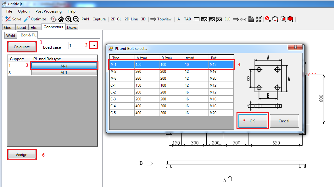
Return [Bolt & PL] tab.
Click [Calculate].
Select [Load Case] is [1].
Under [PL and Bolt type] click bottom and select type [M-1] .
Click [Ok] and [Assign].
Replace for support 8.
Select
Click [Export].
Fill a [File name] "DRW-001" and click [Save].

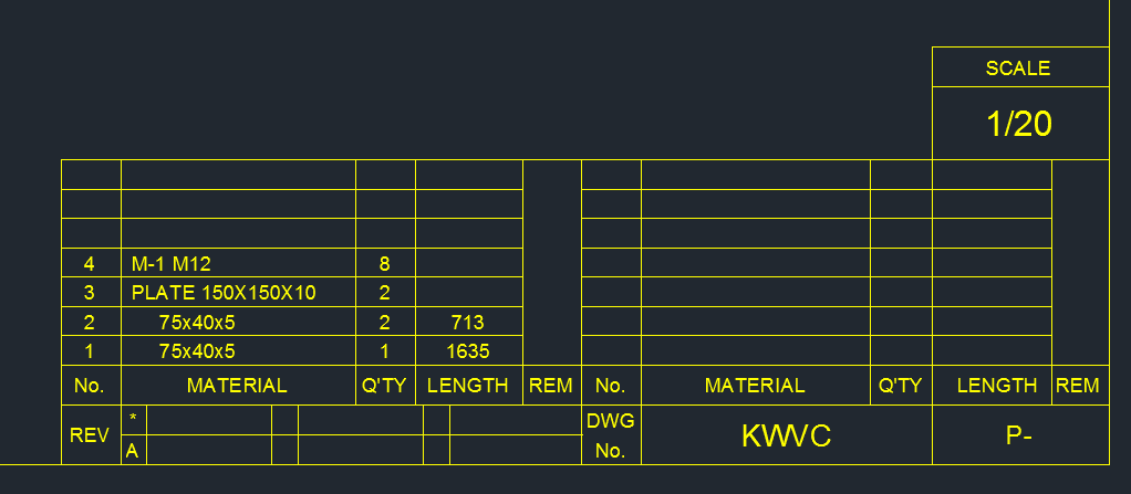
Open DRW-001.dxf file. No. 3 and 4 are plate and bolt.
WELDING
Sample data: Download
Problem: This problem involves using welding tools. The frame has size and loading as show below.

Input model File:
Start SATec and activate the File>Input function of the main menu, to read the model file. The File Manager window appears. Navigate and select the file Model-001.txt.

We have a Model

Create a Section:
Select tab [Ele.] > [Sections], under label [Input] click on drop down box and select [Chanel] ([ ) section.
[Dimension] is select [75x40] and [Thickness] is select [5x7x8x4].
Click [Apply].
Select [3D] view to see 3D model

3D model:

Group element:
In [Ele.] tab click [Element] tab.
Click on [Select]. Screen pick beam G2, G3, G4, G5 and G6. Select [2D_GL] to show a label of beam.

Cick [Accept] to creat a group.
Click [2D_GL] againt and rotate beam G1 1800.

Click [3D] to show a new model.
Create a welding:
Click [Connectors] tab.
Click [Select]. In screen click beam G2.
Choose [Type 1] and check in [Bottom].
In drop down box choose value 1 and click [Apply].
Replace with beam G3, but in drop down box select value [-1].

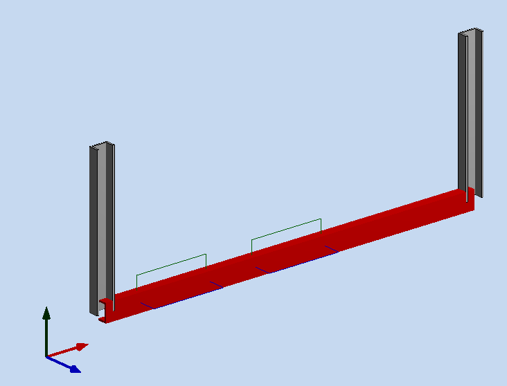
3D model:

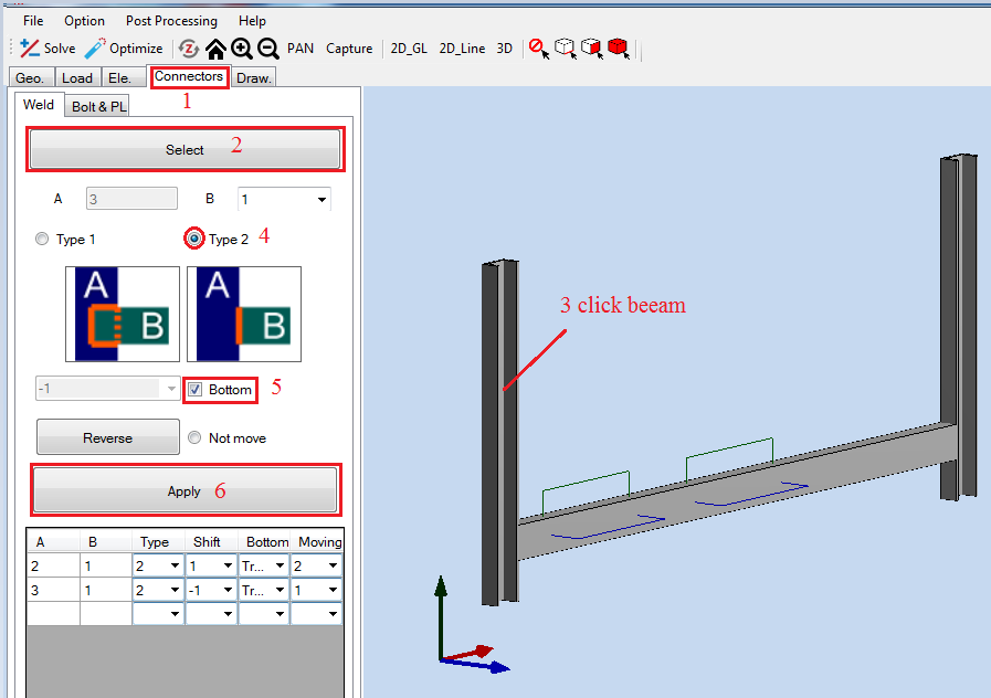
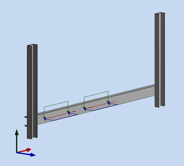
Which Type 2 of welding:
Click [Connectors] tab.
Click [Select]. Screen click beam [G2].
Choose [Type 2] and check in [Bottom].
Click [Apply].
Replace with beam [G3].
Analysis welding:
Click
 and input the File name Welding-001 then click Save
Under Weld tab click Caculate.
Click File > Save.
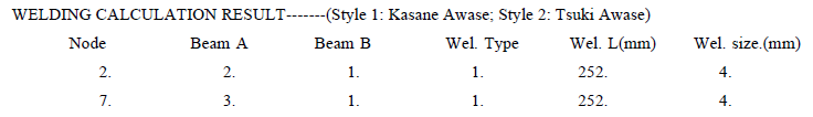
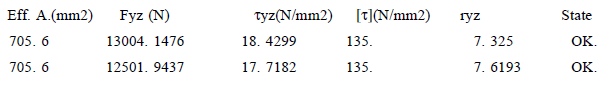
Open file save Welding-001_load 1s.pdf that is welding result file.
Red line is false.
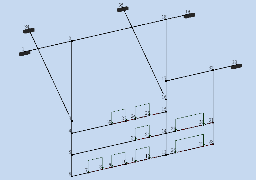
Model 2:
Problem: This problem involves using welding of beam. The frame has size and loading as show below.
Input model file:
Start SATec and activate the File>Input function of the main menu, to read the model file. The File Manager window appears. Navigate and select the file Model-002.txt.
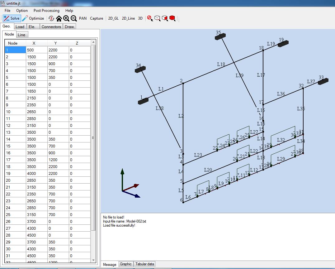
We have a model:
Create a secsion:
Select tab [Ele.] > [Sections], under label [Input] click on drop down box and select [Chanel] ([ ) section.
[Dimension] is select [75x40], and [Thickness] is select [5x7x8x4].
Click [Apply].
Select [3D] view to see 3D model
Replace with two sections:
Square (□): □75x75x1.6
L: L50x50x6x6.5x4.5
ID section:
|
Section |
ID |
|
Chanel |
1 |
|
Square (□) |
2 |
|
L |
3 |
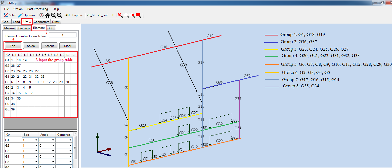
Group element:
In [Ele.] tab click [Element] tab.
Click on [Select]. Screen pick beam from 8 group.
Cick [Accept] to creat a group.
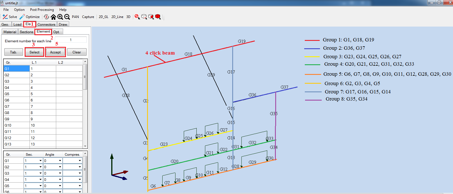
Replace with 8 group:
|
Group |
Beam |
|
1 |
1, 18, 19 |
|
2 |
36, 37 |
|
3 |
23, 24, 25, 26, 27 |
|
4 |
20, 21, 22, 31, 32, 33 |
|
5 |
6, 7, 8, 9, 10, 11, 12, 28, 29, 30 |
|
6 |
2, 3, 4, 5 |
|
7 |
14, 15, 16, 17 |
|
8 |
34, 35 |
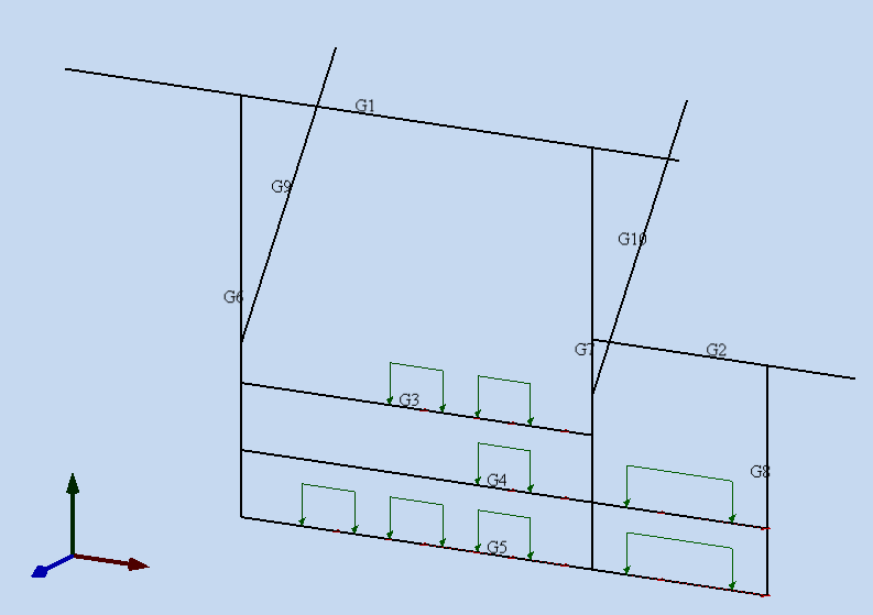
We have 10 beam:

Change the section:
Click drop down [Sec.] and select section [ID] follow tabe
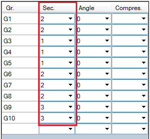
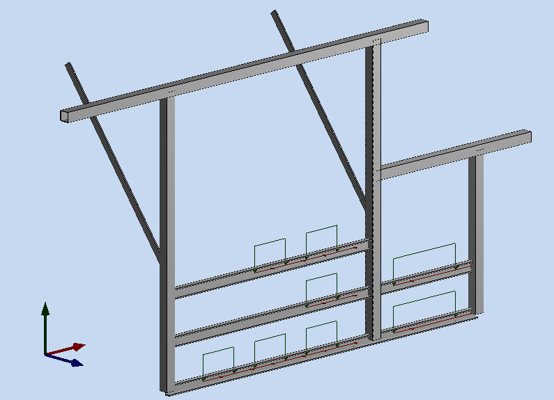
Click on [3D] to show a 3D model:
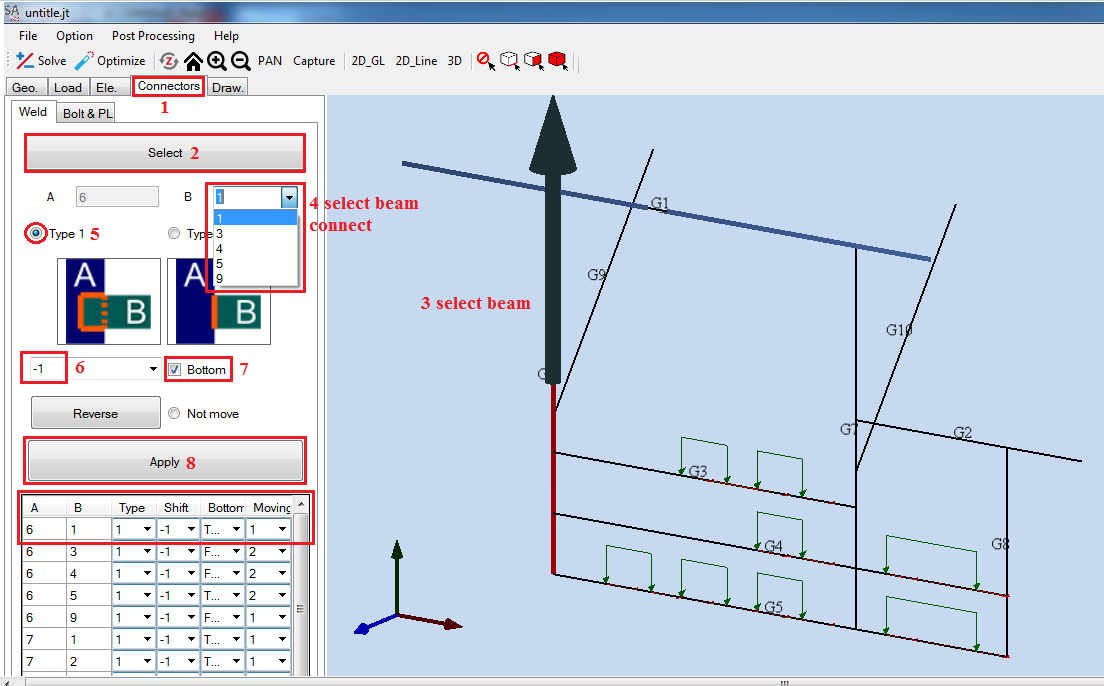
Create a welding:
Click [Connectors] tab.
Click [Select]. Screen click beam G6. G6 will connect with G1, G3, G4, G5 and G9. Click drop down [B] and select beam ID.
Choose [Type 1] and select True or False in [Bottom] follow a table.
In drop down box select [Shift] [1] or [-1] folow a table and click [Apply].
Replace with beam G7, G8 follow a table.
|
Select (A) |
Beam ID (B) |
Type |
Shift (1/-1) |
Bottom (True/False) |
|
G6 |
1 |
1 |
-1 |
True |
|
3 |
1 |
-1 |
False |
|
|
4 |
1 |
-1 |
False |
|
|
5 |
1 |
-1 |
True |
|
|
9 |
1 |
-1 |
False |
|
|
G7 |
1 |
1 |
-1 |
True |
|
2 |
1 |
-1 |
False |
|
|
3 |
1 |
-1 |
False |
|
|
4 |
1 |
-1 |
False |
|
|
5 |
1 |
-1 |
True |
|
|
10 |
1 |
-1 |
False |
|
|
G8 |
2 |
1 |
-1 |
True |
|
4 |
1 |
-1 |
Flase |
|
|
5 |
1 |
-1 |
True |
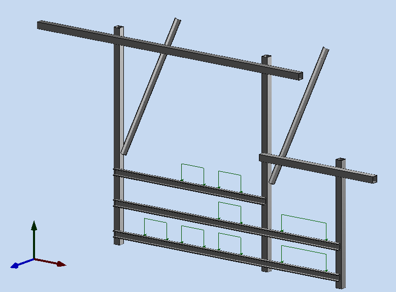
Example with G6:
We have a welding model:
Analysis welding:
Click
and input the [File name] Welding-002 then click [Save]
Under [Weld] tab click [Caculate].
Click [File] > [Save].
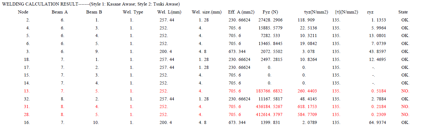
Open file save Welding-002_load 1s.pdf that is welding result file.
Red line is false.
BUCKLING
Sample data: Download
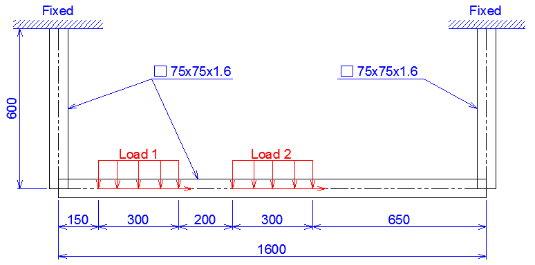
Problem: This problem involves buckling tools. The frame has size and loading as show below.


Input model File:
Start SATec and activate the File>Input function of the main menu, to read the model file. The File Manager window appears. Navigate and select the file Model-001.txt.

We have a Model

Create a Section:
Select tab [Ele.] > [Sections], under label [Input] click on drop down box and select [Chanel] ([ ) section.
[Dimension] is select [75x40] and [Thickness] is select [5x7x8x4].
Click [Apply].

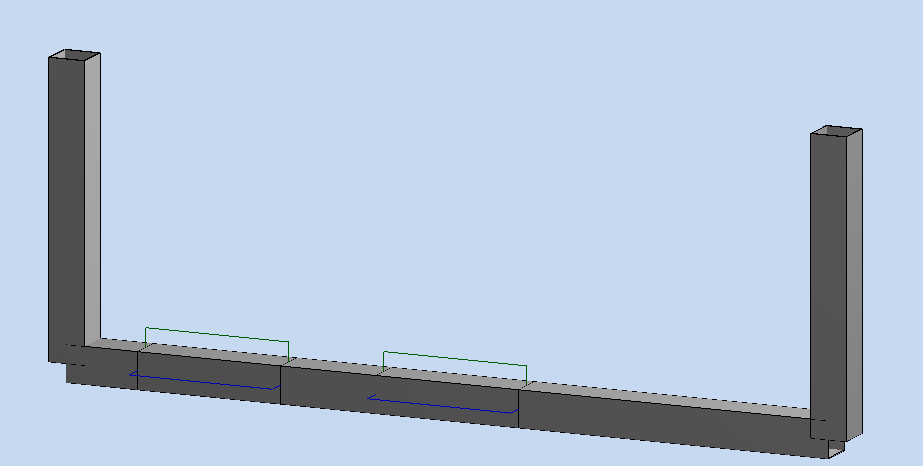
Select [3D] view to see 3D model

3D model:

Group element:
In [Ele.] tab click [Element] tab.
Click on [Select]. Screen pick beam G2, G3, G4, G5 and G6. Select [2D_GL] to show a label of beam.

Cick [Accept] to creat a group.
Click [2D_GL] againt and rotate beam [G1] an angle of [1800].

Create a welding:
Click [Connectors] tab.
Click [Select]. In screen click beam [G2].
Choose [Type 1] and check in [Bottom].
In drop down box choose value [1] and click [Apply].
Replace with beam G3, but in drop down box select value [-1].

We have:
Buckling:
Return [Element] tab, under [Compres.] table select [True] in G1.
Click [Solve].
Fill a [File name] "BUCKLING". Click [Save].
Select [File] > [Save].
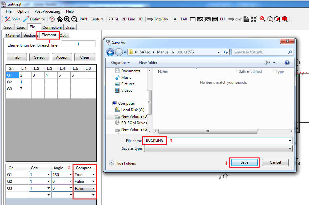
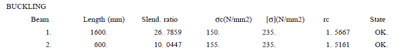
Open file BUCKLING_load 1s.pdf in your save folder that is results file.
ANALYSIS
Sample data: Download
Model 1:
Problem: This problem involves using Analysis and Optimize tools. The frame has size and loading as show below.
Properties of material:
Young's modulus: 206000 N/mm2.
Poission's ratio: 0.3.
Density: 7.86E-6 kg/mm3.
Sections:
Square (□75x75x1.6).
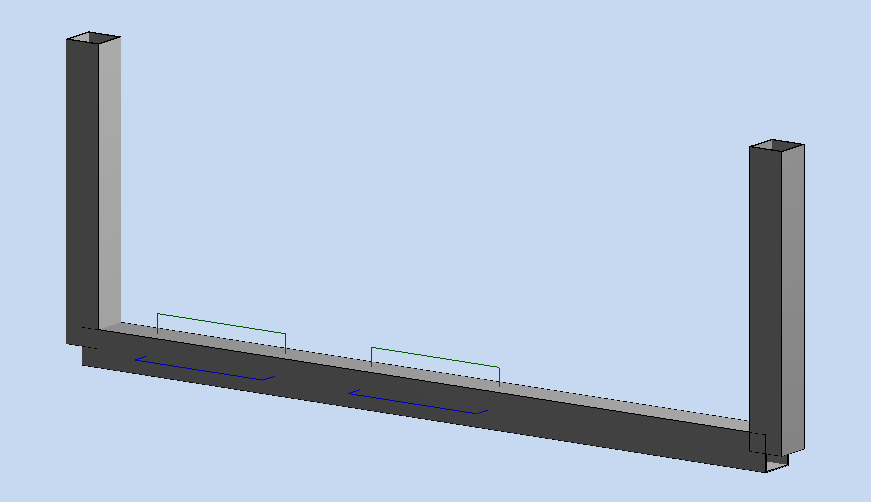
3D model:
Input model File:
Start SATec and activate the [File]>[Input file] function of the main menu, to read the model file. The File Manager window appears and select the file Model-001.txt.

We have a Model
Create a Section:
Select tab [Ele.] > [Sections], under label [Input] click on drop down box and select [Square] section.
[Dimension] is select [75x75] and [Thickness] is select [1.6].
Click [Apply].
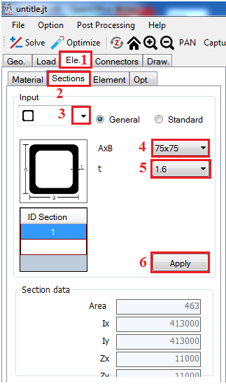
Select [3D] view to show 3D model.

Group element:
In [Ele.] tab click [Element] tab.
Click on [Select]. Screen pick beam G2, G3, G4, G5 and G6. Select [2D_GL] to show a label of beam.
Cick [Accept] to creat a group.

Click on [3D] to show a 3D model:
Analysis:
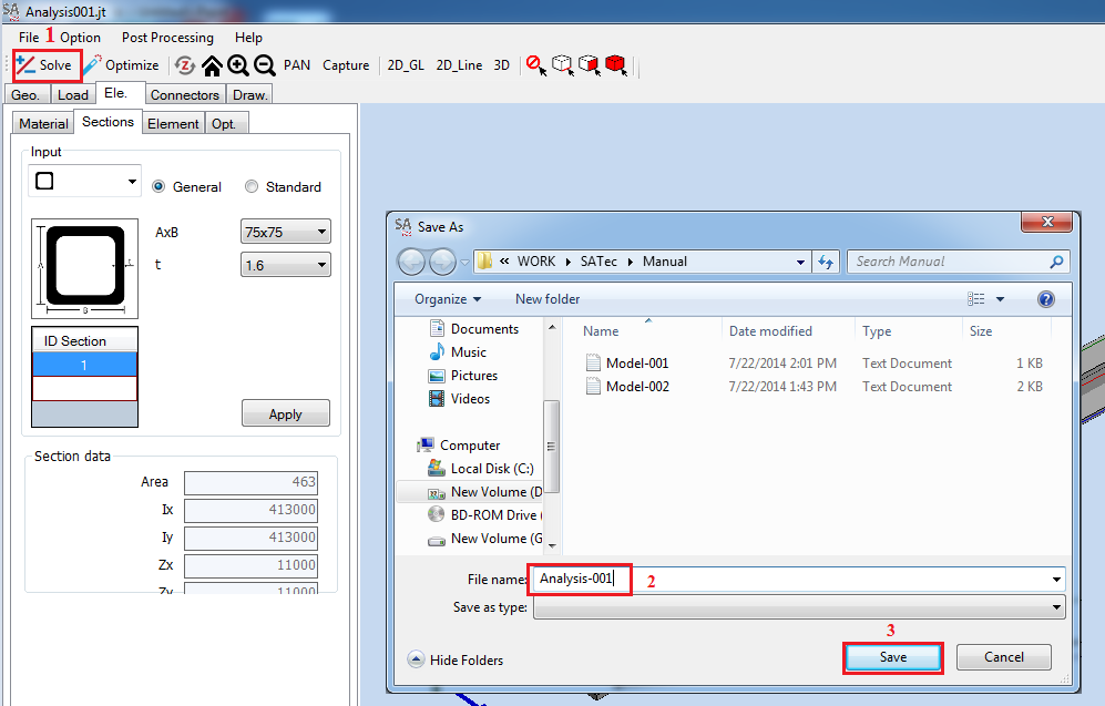
Click [Solve] in menu bar.
Choose Folder and [File name] is Analysis-001 and click [Save].
Click [File] > [Save].
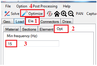
Optimize:
Under tab [Ele.] select tab [Opt.]
Under [Min frequency] fill 15.
Click [Optimize] in menu bar.
Select [File] > [Save].
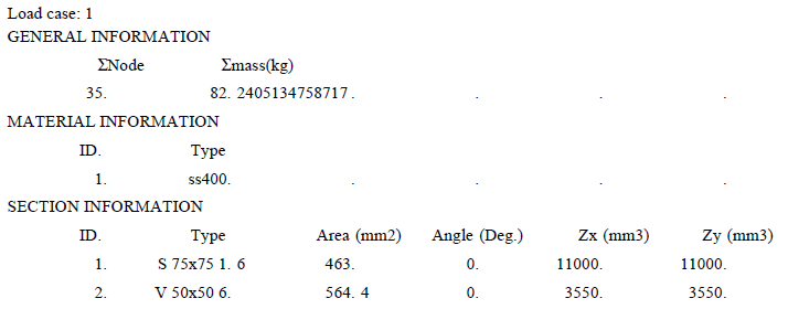
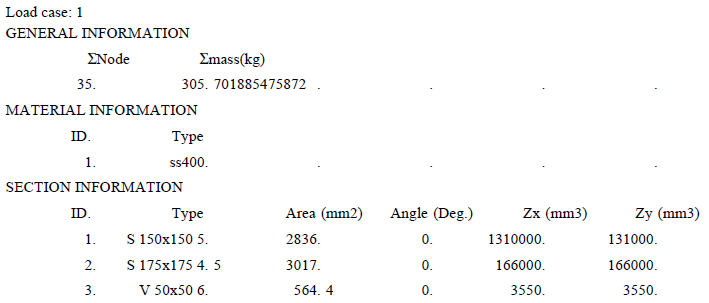
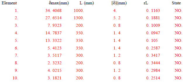
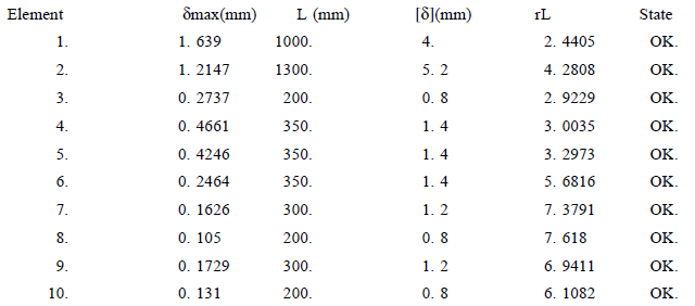
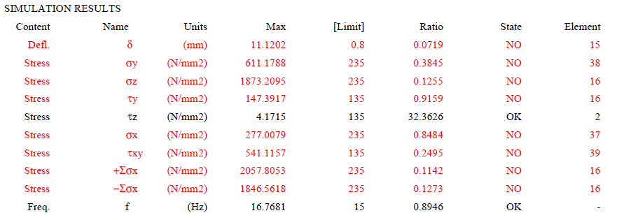
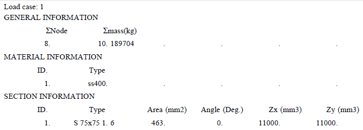
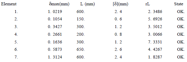
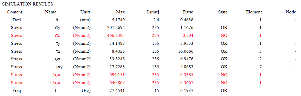
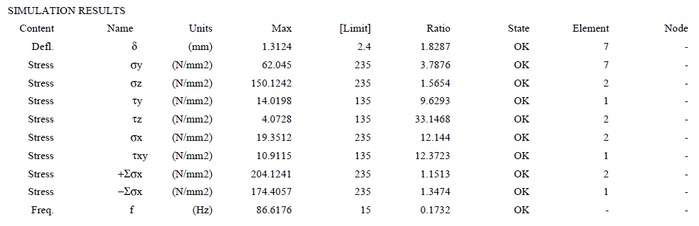
Result file:
Open file Analysis-001_load 1s.pdf and Analysis-001_load 1o.pdf that are results file of Analysis and Optimize.
Red line is false.
|
Section information |
Analysis |
|
|
Optimize |
|
|
|
Displacement |
Analysis |
|
|
Optimize |
|
|
|
Simulation results |
Analysis |
|
|
Optimize |
|


Model 2:
Problem: This problem involves using Analysis and Optimize tools. The frame has size and loading as show below.
Young's modulus: 206000 N/mm2.
Poission's ratio: 0.3.
Density: 7.86E-6 kg/mm3.
Sections:
Square (□75x75x1.6).
L (L50x50x6).
3D model:
Input model file:
Start SATec and activate the [File]>[Input] function of the main menu, to read the model file. The File Manager window appears and select the file Model-002.txt.

Model input:

Create a section:
Select tab [Ele.] > [Sections], under label [Input] click on drop down box and select [Square] section.
[Dimension] is select [75x75], and [Thickness] is select [1.6].
Click [Apply].
Select [3D] view to show 3D model
Replace with section L50x50x6x6.5x4.5.
Group element:
Use a table to make a group. Example: Group 1 include beam G1, G18 and G19.
Click [2D_GL] to show a lable of beam.
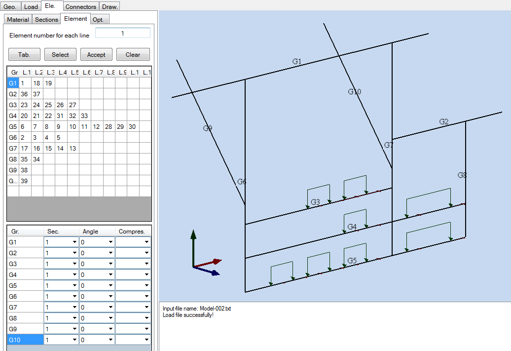
Under tab [Ele.] click tab [Element].
In row [G1] of group table, input 1 in column [L1], input 18 in column [L2] and 19 in column [L3]. Number 1, 18 and 19 are beam ID.
Replace with all group folow a group table.
Click [Tab] to accept all group.
Group table:
|
Group |
Beam ID |
|||||||||
|
L1 |
L2 |
L3 |
L4 |
L5 |
L6 |
L7 |
L8 |
L9 |
L10 |
|
|
G1 |
1 |
18 |
19 |
|
|
|
|
|
|
|
|
G2 |
36 |
37 |
|
|
|
|
|
|
|
|
|
G3 |
23 |
34 |
35 |
36 |
37 |
|
|
|
|
|
|
G4 |
20 |
21 |
22 |
31 |
32 |
33 |
|
|
|
|
|
G5 |
6 |
7 |
8 |
9 |
10 |
11 |
12 |
28 |
29 |
30 |
|
G6 |
2 |
3 |
4 |
5 |
|
|
|
|
|
|
|
G7 |
14 |
15 |
16 |
17 |
|
|
|
|
|
|
|
G8 |
34 |
35 |
|
|
|
|
|
|
|
|
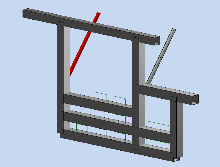
We have 10 beams:
Change the section:
Click drop down [Sec.] and select section [ID].

Click on [3D] to show a 3D model:
Analysis:
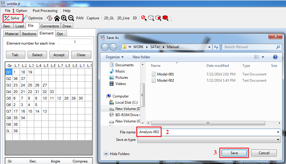
Click [Solve] in menu bar.
Choose Folder and [File name] is Analysis-002 and click [Save].
Click [File] > [Save].
Optimize:
Under tab [Ele.] select tab [Opt.]
Under [Min frequency] fill 15.
Click [Optimize] in menu bar.
Select [File]>[Save].
Result file:
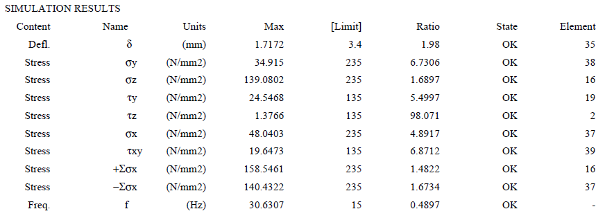
Open file Analysis-002_load 1s.pdf and Analysis-002_load 1o.pdf that are results file of Analysis and Optimize.
Red line is false.
|
Section information |
Analysis |
|
|
Optimize |
|
|
|
Displacement |
Analysis |
|
|
Optimize |
|
|
|
Simulation results |
Analysis |
|
|
Optimize |
 |